Choosing the Right Layer 2 vs Layer 3 Managed Switch for Smart City Networks
Jul 06, 2026
EXECUTIVE SUMMARY
The global shift toward smart cities demands an unprecedented level of network reliability, security, and scalability. At the core of these massive municipal deployments—which integrate critical systems like automated traffic control, high-definition IP surveillance, and IoT sensor arrays—is the network switch. For network architects, research engineers, and system integrators, selecting between a Layer 2 and a Layer 3 managed switch is one of the most foundational architectural decisions.
This technical white paper evaluates the architectural differences, functional boundaries, and optimization strategies for deploying Layer 2 and Layer 3 managed switches within a smart city infrastructure. By understanding where data link bridging ends and network routing begins, engineers can build highly resilient, low-latency, and cost-effective networks.
Architectural Overview: Layer 2 vs Layer 3 Functionality
To optimize smart city topologies, engineers must first align hardware selection with the specific layers of the OSI model where traffic management is required.
Summary Quick Take: While Layer 2 switches operate exclusively at the Data Link Layer using MAC addresses to forward data within a localized segment, Layer 3 switches integrate Routing Layer capabilities, utilizing IP addresses to direct traffic across multiple distinct networks.
Layer 2 Managed Switches: High-Performance Bridging
Layer 2 managed switches operate at the Data Link layer (OSI Layer 2). They forward traffic based on hardware MAC addresses, creating a flat network topology within a single broadcast domain. Modern industrial-grade Layer 2 switches are highly sophisticated, featuring advanced traffic management tools such as VLAN (Virtual Local Area Network) tagging (802.1Q), Quality of Service (QoS/802.1p) prioritization, and Link Aggregation (LACP).
However, because they lack routing capabilities, they cannot pass traffic between different VLANs without an external router. They are inherently designed for localized data distribution where speed and low latency are paramount.
Layer 3 Managed Switches: Hardware-Based Routing
Layer 3 managed switches bridge the gap between traditional switching and routing. Operating at both the Data Link and Network layers (OSI Layers 2 and 3), these devices inspect incoming data packets at the IP address level. Unlike traditional software-driven routers, a Layer 3 switch utilizes specialized Application-Specific Integrated Circuits (ASICs) to perform hardware-based packet routing at wire-speed.
This enables support for advanced routing protocols such as Static Routing, RIP, and OSPF (Open Shortest Path First). By executing inter-VLAN routing directly on the switch fabric, Layer 3 devices eliminate the traffic bottlenecks associated with "router-on-a-stick" architectures.
Smart City Application Matrix: Where to Deploy Each Layer
Smart city networks are inherently distributed, spanning edge sensor deployments to centralized municipal data centers. Deploying the right switch type at the correct network tier prevents structural performance degradation.
Summary Quick Take: Layer 2 switches excel at the edge access tier where high-density device connectivity and raw power distribution are needed, whereas Layer 3 switches are critical at the aggregation and core tiers to manage inter-departmental routing and isolate broadcast traffic.
Network Tier
Recommended Switch Type
Smart City Use Case
Key Technical Requirements
Edge / Access Tier
Layer 2 Managed Switch
IP Camera poles, environmental sensors, smart lighting controllers.
High-power PoE output, surge protection, wide operating temp.
Aggregation / Distribution Tier
Layer 3 Managed Switch
Traffic intersection hubs pooling data from multiple edge cabinets.
Inter-VLAN routing, static routing, high-density fiber uplinks.
Core / Command Center
Layer 3 Backbone Switch
Centralized municipal data centers, emergency response systems.
OSPF/BGP routing, ultra-high throughput (10G/40G), redundant power.
Edge Access and the Role of Power over Ethernet
At the network perimeter, the focus is on raw device onboarding and ruggedized durability. A specialized industrial PoE switch is the ideal candidate for this tier. Because thousands of outdoor endpoints (such as PTZ cameras and IoT gateways) require localized power, an access-tier Layer 2 switch with high-wattage IEEE 802.3bt capabilities ensures seamless integration without the overhead of complex routing tables.
Aggregation and Traffic Segmentation
As data flows from edge cabinets into regional distribution nodes, broadcast traffic scales exponentially. Left unmanaged, a single malfunctioning IP camera could trigger a broadcast storm that paralyzes an entire traffic sector. Here, an industrial gigabit switch with Layer 3 capabilities is deployed to segment networks into isolated subnets (e.g., separating public Wi-Fi from municipal surveillance) while routing critical telemetry data locally to minimize latency.
Key Evaluation Criteria for Research and Engineering Teams
When drafting technical specifications for smart city RFPs, engineering groups must weigh three primary technical variables: network latency, security architecture, and system redundancy.
Summary Quick Take: Network design involves balancing the localized low-latency efficiency of Layer 2 bridging against the granular security boundaries, dynamic failover routing, and traffic control provided by Layer 3 processing.
01 Determinism and Latency
Layer 2 switching introduces near-zero latency because processing is limited to MAC-table lookups. This is critical for real-time applications like connected vehicle telemetry (V2X). However, if traffic must cross a subnet boundary via an external router, latency spikes. Layer 3 switches eliminate this penalty by executing routing inside the ASIC fabric at wire-speed.
02 Granular Network Security
In smart city environments, protecting critical operational technology (OT) from cyber threats is non-negotiable. While Layer 2 devices offer port security and basic Access Control Lists (ACLs), a layer 3 managed switch provides deep network isolation. It enforces IP-based and subnet-based ACLs, preventing unauthorized cross-departmental lateral movement if an edge device is physically compromised.
03 Fault Tolerance and Resiliency
Layer 2 loops are managed via Spanning Tree Protocols (STP/RSTP/MSTP) or specialized industrial ring protocols (ERPS G.8032). While effective, recovery times scale with network size. At Layer 3, dynamic routing protocols like OSPF allow for instantaneous multi-path calculations, routing around network failures dynamically across diverse geographic paths. For mission-critical configurations, you can consult directly with our expert R&D engineering team.
Core White-Label Portfolio Configurations
High-performance OEM/ODM platforms ready for full visual and software stack customization.
RUGGEDIZED DIN-RAIL L3
IES7511-8PGE2GF-4BT-DC
Managed 8 Port Gigabit Industrial PoE++ Switch With 2 Gigabit SFP Uplink
4-10/100/1000Mbps RJ45 ports with PoE++ (Port 1-4, up to 90W)
4-10/100/1000Mbps RJ45 ports with PoE+ (Port 5-8)
ERPS(G.8032) STP/RSTP/MSTP for Ring network protection
Layer 3 static routing (IPv4 and IPv6) for inter VLAN routing
Supports contact discharge of ±8KV DC and air of ±15KV
Din Rail mounting installation with redundant power input
View Detail →
COMPACT INDUSTRIAL L3
IES7511-4PGE2GF-DC
Managed 4 Port Gigabit Industrial PoE Switch With 2 Gigabit SFP Uplink
4 ports supporting PoE+ to PD device (IEEE 802.3af/at standard)
Supports PoE power up to 30 watts for each PoE port
ERPS(G.8032) STP/RSTP/MSTP for Ring network and Link protection
Layer 3 static routing (IPv4 and IPv6) for inter VLAN local routing
IGMP Snooping, IGMP Querier and IGMP Fast Leave for multicast
Include VLANs, PoE scheduling, ACLs, DiffServ, LACP, MVR and DHCP
View Detail →
10G UPLINK FIBER AGGREGATION
S7500-24GF8GEC4TF-L3M
24 Port Gigabit SFP Fiber Managed Switch With 4-10G SFP+ Uplink
16 high-speed Gigabit SFP ports for flexible fiber connectivity
8 Gigabit RJ45/SFP combo ports for diverse link options
4 versatile 1G/2.5G/10G SFP+ uplink interfaces for future-proofing
Static and dynamic routing with support for IPv4/IPv6, RIP, OSPF
Enhanced security through SSH, ACLs, 802.1X, RADIUS, and TACACS+
High-performance switching with 256Gbps backplane bandwidth
View Detail →
25G CORE HYBRID BACKBONE
S7500-16TE12TF4DF-EI
16 x 10Gbps RJ45, 12 x 10Gbps SFP+, 4 x 25Gbps SFP28 Hybrid Switch
16- 10Gb RJ45 Ethernet ports enable ultra smooth data connections
12- 10Gb SFP+ interfaces for enhanced heavy core fiber routing
4- 25Gb SFP28 high-speed uplinks to prevent core infrastructure bottlenecks
Dual power supply (1+1) ensures absolute hardware redundancy
Full IPv4/IPv6 routing capabilities with RIP, OSPF, BGP, PIM, ISIS, VRRP
Massive bandwidth processing capacity up to 760Gbps throughput
View Detail →
Conclusion: Engineering an Optimized Network Blueprint
Smart city networks are not monocultures; they require a hybrid, tiered approach to hardware selection. Access networks distributed across physical urban landscapes should leverage ruggedized Layer 2 switches to minimize cost and maximize edge density. Concurrently, the aggregation and core infrastructures must utilize high-performance Layer 3 architectures to maintain structural isolation and dynamic fault recovery.
For system integrators selecting an OEM/ODM manufacturing partner, ensuring access to a comprehensive portfolio—ranging from edge-optimized white label network switches to advanced Layer 3 distribution units—is critical. Aligning hardware capabilities directly with OSI model requirements allows municipalities to deploy scalable, secure, and future-proof urban infrastructure.
Looking for a Reliable Industrial Network Hardware Partner?
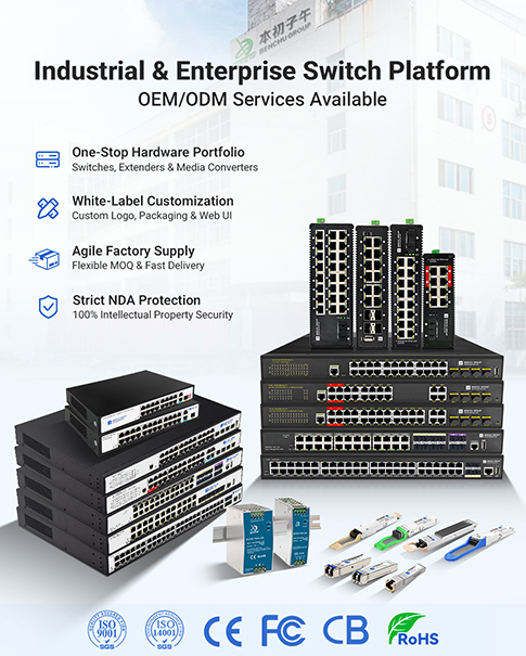
From customized firmware Web-UI and custom private logos to 6KV surge protection, we provide flexible OEM/ODM networking and PoE solutions with low MOQ for global brand owners and integrators.
Contact Our Engineering Team & Request a Sample
Read More

 E-Mail Us
 Call Us
 Address


 IPv6 network supported
 English