Leave A Message
If you are interested in our products and want to know more details,please leave a message here,we will reply you as soon as we can.

FAQ
Many industrial switches offer dual power inputs for redundancy.
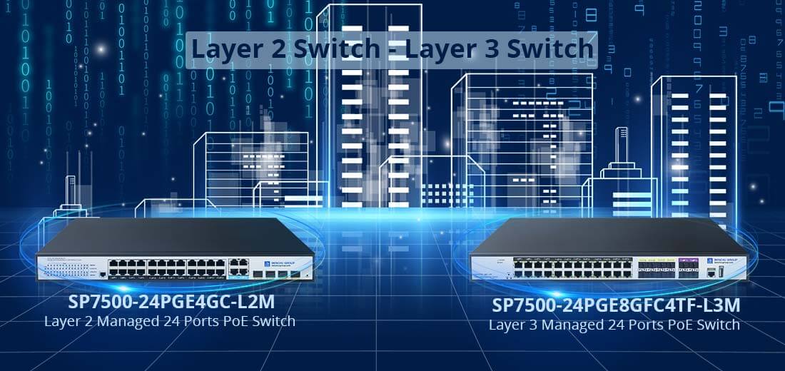
Layer 2 switch: Layer 2 switches work in the second layer (data link layer) of the OSI model, identifying MAC address information in data packets, forwarding them based on MAC addresses, and recording these MAC addresses and corresponding ports in an internal address table. Therefore, layer 2 switches require strong data recognition and forwarding capabilities.
The second layer switch relies on information in the link layer (such as MAC addresses) to complete line speed exchange between data from different ports. Its main functions include physical addressing, error checking, frame sequencing, and data flow control. Desktop switches generally do not have a high level of work complexity and are located at the bottom of the network, so they only need to provide the most basic data link functions. In addition, some enterprise level layer 2 switches can implement VLAN, DHCP relay, QoS and port security, port mirroring, and other functions.
When a switch receives a packet from a certain port, it first reads the source MAC address in the packet header, so that it knows which port the machine with the source MAC address is connected to; Read the destination MAC address from the packet header and search for the corresponding port in the address table; Copy the data packet directly to the port corresponding to the destination MAC address in the table; If the corresponding port cannot be found in the table, the packet will be broadcasted to all ports. When the destination machine responds to the source machine, the switch can learn which port the destination MAC address corresponds to, and no longer need to broadcast to all ports when transmitting data next time.
Layer 3 switch: Layer 3 switch is essentially a special type of router that focuses on switching in performance and is inexpensive. Traditional switching technology operates at the second layer of the OSI network standard model - the data link layer, while layer 3 switches are designed for IP, with simple interface types and strong layer 2 packet processing capabilities. They can work at the third layer of the protocol to replace or partially complete the functions of traditional routers, while also having almost the speed of layer 2 switching and relatively cheap prices.
Working principle of layer 2 switch: When the switch receives a data packet from a certain port, it first reads the source MAC address in the packet header, so that it knows which port the machine with the source MAC address is connected to; Read the destination MAC address from the packet header and search for the corresponding port in the address table; Copy the data packet directly to the port corresponding to the destination MAC address in the table; If the corresponding port cannot be found in the table, the packet will be broadcasted to all ports. When the destination machine responds to the source machine, the switch can learn which port the destination MAC address corresponds to, and no longer need to broadcast to all ports when transmitting data next time.
Working principle of layer 3 switch: Generally speaking, large local area networks are divided into smaller ones based on functional or geographical factors. Usually, LANs are connected through routers, which enables VLAN (Virtual Local Area Network) technology to be widely used in networks. However, the routing capability of traditional ordinary routers is too weak. Simply using routers to achieve inter network access has a limited number of ports and slow routing speed, which limits the size and access speed of the network. If gigabit or 100Mbps ports on a layer 3 switch are used to connect different subnets or VLANs, it economically solves the problem of relying on routers for communication between subnets after subnet partitioning while maintaining performance.
The difference between layer 3 switches and layer 2 switches is that layer 3 switches work at the third layer (network layer) of the OSI model, while layer 2 switches work at the second layer (data link layer) of the OSI model.
Layer 2 switches can recognize the MAC address information in data packets, forward them based on the MAC address, and record these MAC addresses and corresponding ports in an internal address table. Layer 3 switching technology is the addition of layer 3 forwarding technology to layer 2 switching technology to achieve high-speed packet forwarding and accelerate data exchange within large local area networks.
A wants to send data to B. If the destination IP is known, A uses a subnet mask to obtain the network address and determines whether the destination IP is in the same network segment as itself. If they are in the same network segment but do not know the MAC address required to forward the data, A sends a request and B returns its MAC address. A uses this MAC to encapsulate the data packet and sends it to the switch. The switch uses a layer 2 switching module to look up the MAC address table and forward the data packet to the corresponding port.
If the destination IP address is not in the same network segment and there is no corresponding MAC address entry in the stream cache entry, the first normal packet will be sent to a default gateway corresponding to the third layer routing module. Then the three-layer module receives this packet, queries the routing table to determine the route to B, and the three-layer switch plays the role of routing and forwarding. When the corresponding relationship between the MAC addresses and forwarding ports of hosts A and B is subsequently established, the subsequent data from A to B is directly handed over to the layer 2 switching module for completion. This is commonly referred to as multiple forwards per route.
Flow control ensures smooth data transmission by preventing packet loss during congestion.
Unmanaged switches are plug-and-play, while managed switches require configuration.
Basic tools like Ethernet cables, a power source, and mounting brackets (if wall or rack-mounted).
Yes, with high switching capacities and bandwidths, they handle intensive traffic.
1. Upgrade to a Higher PoE Power Switch
Solution: If your current PoE switch doesn’t provide enough power, consider upgrading to a switch with a higher total power budget. PoE standards vary:
--- PoE (802.3af):Up to 15.4W per port
--- PoE+ (802.3at): Up to 30W per port
--- PoE++ (802.3bt): Up to 60W (Type 3) or 100W (Type 4) per port
Benefit: This allows more power-hungry devices like IP cameras, access points, or VoIP phones to operate efficiently.
2. Use PoE Injectors
Solution: For individual devices that need more power, a PoE injector can supplement the power provided by your PoE switch. Injectors provide additional power directly to specific devices without requiring a full switch upgrade.
Benefit: It’s a cost-effective way to increase power for high-demand devices.
3. Use Managed PoE Switches with Power Management Features
Solution: Managed PoE switches allow you to allocate power based on priority. For example, you can prioritize power delivery to critical devices (such as security cameras) while limiting power to less important devices.
Benefit:You ensure that essential devices receive adequate power without overloading the budget.
4. Reduce the Number of High-Power Devices
Solution: Evaluate the connected devices and remove or replace devices that require more power than the switch can handle. Consider using energy-efficient devices that consume less power.
Benefit:You can maintain performance without exceeding the available power.
5. Balance Device Power Consumption Across Multiple Switches
Solution: Distribute your PoE devices across multiple switches to avoid overloading a single switch's power budget.
Benefit: This spreads the load and ensures that each switch operates within its power budget.
6. Check for Cabling Issues
Solution: Poor cabling can cause power loss during transmission. Ensure you’re using proper Category 5e or better Ethernet cables to minimize power loss and maximize efficiency.
Benefit:This can improve power delivery without changing your switch.
7. Monitor PoE Power Usage
Solution: Regularly monitor your PoE switch’s power consumption using network management tools or the switch's interface. Identify and address potential overload issues before they affect performance.
Benefit: Proactive management avoids sudden power shortages.
Conclusion
To solve the problem of insufficient PoE power budget, assess your current infrastructure, upgrade hardware if necessary, and use management tools to optimize power allocation. By strategically managing the power needs of your devices, you can ensure smooth and efficient operation.
Traffic shaping and management protocols mitigate overload effects.
When devices aren't powering on via Power over Ethernet (PoE), the issue could stem from various sources. Here's a systematic troubleshooting guide to help you resolve the problem:
1. Check the PoE Power Budget
Explanation: Ensure that your switch or injector has enough available power to supply all connected PoE devices. If the power consumption exceeds the switch's PoE budget, some devices may not power on.
Solution: Verify the total PoE power budget of the switch and compare it to the power requirements of each connected device.
2. Verify PoE Standards Compatibility
Explanation: Devices may not power on if the PoE switch and the devices use different PoE standards (e.g., IEEE 802.3af, 802.3at, or 802.3bt).
Solution: Confirm that both the switch and the powered device (PD) support the same PoE standard. If the device requires 802.3at or 802.3bt and the switch only provides 802.3af, it may not work.
3. Test with a Known Good Cable
Explanation: Faulty or low-quality Ethernet cables may interfere with the PoE power delivery.
Solution: Replace the cable with a high-quality Cat5e or Cat6 cable that supports PoE. Ensure the cable length is within the recommended limit (usually under 100 meters for PoE).
4. Check Switch PoE Port Configuration
Explanation: Some managed switches allow you to enable or disable PoE on individual ports, or they may have port-specific power limits.
Solution: Log into the switch’s management interface and verify that PoE is enabled on the port connected to the device. Also, check if any power limit settings are applied.
5. Examine Device Power Requirements
Explanation: Some devices require more power than others, and if a switch cannot supply the necessary wattage, the device will not power on.
Solution: Check the device's power consumption rating and confirm that the switch can provide adequate wattage to meet that requirement.
6. Inspect for Physical Damage
Explanation: Damaged Ethernet ports or cables can prevent proper power transmission.
Solution: Inspect both the device and switch ports for bent pins or other visible damage. Try using a different port or a different device to rule out hardware failure.
7. Reboot the PoE Switch or Injector
Explanation: A software issue or temporary power surge may have caused the switch to stop supplying power to the ports.
Solution: Power cycle the switch or PoE injector by unplugging it from the power source for 30 seconds, then reconnecting it.
8. Use a PoE Tester
Explanation: A PoE tester helps determine whether the switch is supplying power to the connected device.
Solution: Connect a PoE tester between the switch and device to measure the voltage and verify whether the proper power is being supplied.
9. Update Firmware
Explanation: Firmware bugs in PoE switches can cause power delivery issues.
Solution: Check the manufacturer’s website for any firmware updates for the switch and update if necessary.
10. Replace Faulty Equipment
Explanation: If you've ruled out other causes, the PoE port on the switch or the device itself could be faulty.
Solution: Try connecting the device to another PoE port or switch, or use another device to see if the problem persists. Replace any faulty components.
By following these steps, you should be able to identify and resolve the issue of devices not powering on via PoE.
Yes, they comply with RoHS and feature energy-efficient technologies.
Overheating in PoE switches can cause performance degradation, shorter hardware lifespan, or complete failure. To solve the overheating problem and prevent future occurrences, follow these steps:
1. Check Ventilation and Airflow
Explanation: Poor ventilation can cause heat buildup in the switch, leading to overheating.
Solution:
--- Ensure the switch is installed in a well-ventilated area.
--- Maintain at least 2-4 inches of clearance on all sides, especially around air vents.
--- Avoid stacking switches or placing them near other heat-generating equipment.
--- If mounted in a rack, ensure adequate airflow and ventilation at both front and rear ends.
2. Ensure Proper Cooling in the Room
Explanation: High ambient temperatures in the server or wiring room can exacerbate overheating.
Solution:
--- Install air conditioning or improve airflow in the room.
--- Ensure that the room's temperature is maintained within the switch’s operating range (typically between 32°F - 113°F / 0°C - 45°C, but check your switch’s specifications).
--- Use fans or cooling systems specifically designed for data centers or server rooms.
3. Clean Dust and Debris
Explanation: Dust can block air vents and fan blades, reducing the switch’s ability to dissipate heat.
Solution:
--- Regularly clean the switch’s air vents, fans, and surroundings to ensure proper airflow.
--- Use compressed air or a soft brush to clean dust and debris from air intake and exhaust vents.
--- Schedule periodic maintenance to prevent dust accumulation.
4. Verify PoE Power Load
Explanation: PoE switches that are fully loaded with high-powered PoE devices (e.g., cameras, access points) generate more heat than when lightly loaded.
Solution:
--- Check the power budget of the switch and verify that it is not being overloaded. If the power consumption is near the maximum, it may generate excessive heat.
--- Spread the power load across multiple switches if possible to reduce the burden on a single switch.
--- Consider upgrading to a switch with a higher PoE power budget if needed.
5. Upgrade Firmware
Explanation: Firmware updates can improve the switch’s power and temperature management.
Solution:
--- Check for firmware updates from the manufacturer that might include fixes for overheating or power management issues.
--- Apply any available updates to optimize the switch's thermal performance.
6. Monitor the Switch's Temperature
Explanation: Some managed PoE switches provide real-time temperature monitoring and alerts for overheating.
Solution:
--- Log into the switch’s management interface and check the temperature readings.
--- Set up email or SNMP alerts to notify you if the switch’s temperature exceeds safe operating limits.
7. Check Fan Operation (If Applicable)
Explanation: Some PoE switches come with built-in fans for cooling. If these fans fail, overheating may occur.
Solution:
--- If your switch has fans, listen for any unusual noises or absence of fan noise. A faulty fan could cause overheating.
--- Check the fan status in the switch's management interface (if available) or physically inspect the fans.
--- Replace malfunctioning fans as necessary.
8. Consider a Fan Tray or External Cooling
Explanation: For environments where the ambient temperature is difficult to control, additional cooling might be required.
Solution:
--- Install a rack-mounted fan tray to provide extra cooling for the switch.
--- Use external cooling systems like portable fans or cooling units to dissipate heat from the switch.
9. Reduce PoE Usage During Peak Heat
Explanation: During hot days or in environments without effective cooling, the combination of heat and high PoE power consumption can lead to overheating.
Solution:
--- Temporarily reduce the number of connected PoE devices or limit high-power PoE usage during peak heat times.
--- Schedule intensive tasks (like device restarts or firmware updates) for cooler periods of the day.
10. Replace the Overheating Switch
Explanation: If a switch consistently overheats even after following the above steps, it may be defective or undersized for your environment.
Solution:
--- Consider replacing the switch with a more heat-tolerant model or one with better cooling mechanisms.
--- Choose industrial-grade PoE switches if the switch is deployed in harsh or high-temperature environments, as they are designed to withstand more extreme conditions.
By addressing the factors contributing to overheating—such as poor ventilation, excessive PoE power load, and dust accumulation—you can prevent the PoE switch from overheating and ensure stable performance.
Directly from their official website or authorized distributors globally.
 E-Mail Us
 Call Us
 Address
5F, Block5, GuangmingGu Industrial Park, Matian Villiage, Guangming Disitrict, Shenzhen, China



 IPv6 network supported
 English